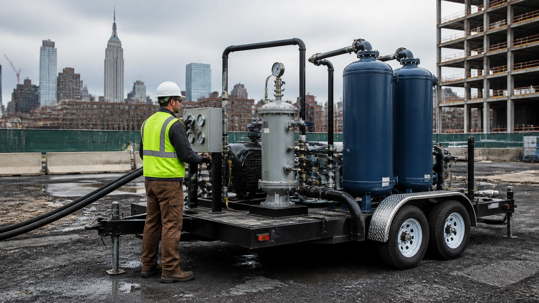
A soil vapor extraction system can remove volatile organic compounds (VOCs) from unsaturated soil without excavating the entire source area. That matters on dense, active sites across New York City, Hudson County, Newark, Jersey City, and northern New Jersey, where excavation may disrupt structures, utilities, streets, or ongoing operations.
SVE is not a plug-and-play equipment package. The system must match the site’s geology, contaminant profile, depth to groundwater, building conditions, and regulatory endpoint.
“A vacuum only works when the site lets air move.”
That is the central design issue. Before selecting a blower or treatment vessel, the project team needs to understand how air will move through the vadose zone: and where it will not.
What a Soil Vapor Extraction System Does
SVE applies a vacuum to extraction wells screened in the unsaturated zone above the water table. The vacuum creates pressure gradients that draw soil gas through the pore spaces. VOCs partition into that moving air and travel through subsurface piping to an aboveground treatment system.
A typical system includes:
- SVE extraction wells and wellheads
- Individual conveyance lines and a common manifold
- Isolation and throttling valves
- Vacuum blower or regenerative blower
- Moisture knockout or air-water separator
- Particulate filtration
- Granular activated carbon or thermal treatment
- Pressure, flow, and temperature instruments
- Influent and effluent vapor sampling ports
- Controls, alarms, and emergency shutdowns
SVE works best when contaminants are sufficiently volatile and the soil has enough permeability to support airflow. Sands and gravels generally respond better than tight clays, silts, or heavily stratified fill. Low-permeability layers can limit the radius of influence and leave isolated pockets of contamination untreated.
SVE also has limits. It may not adequately address contamination below the water table, highly sorbed compounds, free product, or areas where utilities and foundations create preferential pathways. In those cases, the remedy may require air sparging, excavation, in-situ treatment, groundwater recovery, vapor intrusion mitigation, or a combined approach.
For building-related concerns, SVE should be coordinated with a broader vapor intrusion mitigation evaluation. Removing VOC mass from soil is source control. It does not automatically prove that indoor air is protective.
Start With the Conceptual Site Model
The first design document should not be a blower specification. It should be a defensible conceptual site model (CSM).
For a New York or New Jersey property, the CSM should address:
- VOC source areas and historical operations
- Soil types, fill conditions, and stratigraphy
- Depth to groundwater and seasonal fluctuations
- Contaminant concentrations by depth
- Building slabs, basements, crawl spaces, and occupied areas
- Underground utilities and other preferential pathways
- Nearby receptors and potential off-site migration
- Existing monitoring wells, borings, and soil vapor points
- Expected remedial standards and closure requirements
A Phase II investigation may include soil borings, groundwater sampling, soil vapor points, sub-slab sampling, and indoor air testing. Envicon’s environmental assessment team uses these data to determine whether SVE is technically appropriate and how it should fit into the overall remedial strategy.
The CSM also establishes whether the target is contaminant mass removal, risk reduction, protection of indoor air, achievement of soil cleanup objectives, or a combination of these goals.

Pilot Testing Establishes the Design Basis
The most important SVE parameters should come from field testing, not generic spacing tables.
A pilot test can evaluate:
- Applied vacuum at the extraction well
- Flow rate at the wellhead
- Radius of influence (ROI)
- Vacuum response at nearby monitoring points
- Air permeability and preferential pathways
- VOC concentrations in extracted soil gas
- Condensate generation
- Potential short-circuiting through utilities or fractures
A step-vacuum or step-flow test typically starts at a controlled operating condition and increases the applied vacuum or extraction rate while measuring the response at surrounding points. The results show whether the target zone receives meaningful vacuum and whether the system is pulling air from the intended subsurface interval.
For example, a well may show a strong vacuum response nearby but little response across a clay lens. That is not a minor operating detail. It may require additional wells, deeper screened intervals, pulsed operation, soil blending, or another remedial technology.
The pilot test should support the final design memorandum or remedial work plan. It should explain why the well spacing, operating range, treatment capacity, and performance criteria are appropriate for the site.
Vacuum Blower Design: Flow Is Only Half the Question
A blower must deliver the required airflow at the required vacuum. A high-cfm blower that cannot maintain vacuum through the piping and treatment train will not produce a reliable remedy.
Blower selection should account for:
- Number of extraction wells operating at one time
- Expected flow per well
- Required wellhead vacuum
- Piping length, diameter, and fittings
- Pressure losses through filters and treatment vessels
- Condensate and moisture loading
- Treatment system backpressure
- Future operating changes as VOC concentrations decline
- Electrical service and noise limitations
- Required redundancy and emergency shutdown controls
The design should include enough control at each well to balance the system. Individual isolation valves and throttling valves allow the operator to focus extraction on active source areas rather than wasting capacity on wells that have reached diminishing returns.
Variable-frequency drives can provide additional flexibility where the system must operate across a broad range of flow and vacuum conditions. Smaller or more stable systems may use regenerative blowers with a narrower performance envelope.
The system should also include pressure gauges or transmitters at the wells, manifold, blower inlet, and treatment stages. Flow meters help identify declining extraction, blocked lines, leaks, or a well that is drawing excessive air compared with the rest of the system.
Vapor Treatment: Carbon Adsorption or Thermal Oxidation?
Extracted soil gas contains VOCs. It cannot simply be discharged without evaluating emissions, treatment requirements, and applicable air regulations.
Granular activated carbon adsorption
Granular activated carbon (GAC) is common for low-to-moderate VOC concentrations and smaller SVE systems. The carbon adsorbs VOCs as contaminated air passes through the vessel.
A properly designed carbon train generally includes:
- Moisture knockout upstream of the carbon
- Particulate filtration
- One or more carbon vessels
- Sampling ports before and after treatment
- Pressure-drop monitoring
- A planned changeout or regeneration schedule
Two vessels in series provide a practical operating arrangement. The first vessel captures most of the VOC mass, while the second acts as a polishing vessel and helps identify breakthrough before treated air exceeds the project limit.
Carbon capacity depends on VOC type, concentration, flow rate, humidity, temperature, and competing compounds. A carbon vessel that performs well during startup may load faster than expected if groundwater intrusion, high humidity, or concentrated source-area vapors enter the system.
Spent carbon must be managed appropriately. Disposal, regeneration, manifests, and waste classification belong in the operating plan: not as an afterthought.
Thermal or catalytic oxidation
Thermal oxidation destroys VOCs rather than transferring them to a solid media. It may be appropriate for higher concentrations, larger air volumes, or projects where carbon changeout would become inefficient.
A thermal treatment system can include:
- Combustion chamber and burner
- Combustion air controls
- Temperature monitoring
- Flame-failure and high-temperature interlocks
- Heat recovery equipment
- Stack and emissions monitoring
- Automated shutdown controls
Thermal oxidation usually requires more capital, energy, permitting, and operational oversight than GAC. The design must account for residence time, temperature, VOC loading, heating value, combustion byproducts, and applicable air emission limits.
In New Jersey, the project team should evaluate air permitting under N.J.A.C. 7:27 and coordinate the treatment system with NJDEP requirements before equipment installation. Permit applicability depends on the specific equipment, emissions, control device, and operating conditions.
New York Regulatory Coordination
In New York, SVE design and operation typically fit within the NYSDEC site investigation and remediation framework, including DER-10 technical guidance and applicable soil cleanup objectives.
Where vapor intrusion is part of the exposure pathway, the project should also follow the NYSDEC vapor intrusion guidance and the New York State Department of Health soil vapor intrusion guidance.
The remedial design should define:
- Extraction well construction and screened intervals
- Pilot test results and ROI
- Blower operating range
- Vapor treatment and emissions controls
- Sampling locations and analytical methods
- Startup and shutdown procedures
- Performance monitoring frequency
- Contingency actions
- Criteria for optimization and system termination
On NYC properties, coordination may also involve NYC OER, E-Designation requirements, NYC Parks, building owners, construction managers, and local utility stakeholders. The system needs to function in the real site environment: not just on the design drawing.
New Jersey Regulatory Coordination
In New Jersey, the remedial approach must align with the Technical Requirements for Site Remediation under N.J.A.C. 7:26E.
The SVE design should be documented in the appropriate remedial action work plan and supported by site data. Performance and closure should be evaluated under NJDEP’s Technical Guidance for the Attainment of Remediation Standards.
NJDEP’s Vapor Intrusion Pathway guidance is used to evaluate soil gas, sub-slab, and indoor air conditions. SVE may reduce the source, but the project still needs to demonstrate that the vapor intrusion pathway is controlled for current and future receptors.
That may involve continued monitoring or a separate sub-slab depressurization system, especially where VOCs remain in groundwater or beneath an occupied building.
Operating and Optimizing the System
Startup should proceed methodically:
- Inspect wells, piping, valves, vessels, electrical systems, and alarms.
- Confirm that condensate handling is operational.
- Open well valves according to the approved startup sequence.
- Start the blower at a controlled condition.
- Record vacuum and flow at each operating well.
- Collect baseline influent and effluent vapor data.
- Confirm treatment performance before normal operation.
- Adjust valves to balance extraction across the treatment area.
Routine monitoring should track:
- Wellhead vacuum and flow
- Blower inlet conditions
- VOC concentrations in influent and effluent vapor
- Carbon vessel pressure drop
- Carbon breakthrough indicators
- Condensate volume and disposal
- Ambient air near the treatment area
- Indoor air or sub-slab conditions where applicable
- Changes in subsurface vacuum response
SVE performance often declines over time. That does not automatically mean the remedy has failed. It may indicate that the easily removed VOC mass is gone and the system needs optimization.
Common optimization steps include:
- Taking completed wells offline
- Reducing flow in low-concentration areas
- Increasing focus on persistent source zones
- Adjusting vacuum to limit excess dilution air
- Repairing leaks or blocked lines
- Adding extraction points where the ROI is incomplete
- Using pulsed operation to allow contaminant rebound
- Conducting rebound testing before shutdown
“The goal is not to run equipment longer. The goal is to prove the site is moving toward closure.”
Why Project Leadership Matters
A soil vapor extraction system connects subsurface investigation, mechanical design, air emissions, field operations, laboratory data, and regulatory coordination. When those pieces sit with separate teams, issues move slowly and accountability becomes unclear.
Envicon keeps the work connected. Our team provides field-level oversight, direct agency coordination, technical documentation, and practical recommendations that help developers, attorneys, contractors, and property owners make decisions faster.
We do not just deliver a report. We build a clear path from investigation to operation, optimization, and regulatory closure. Our digital project tools can also provide real-time visibility into field activity, deliverables, schedules, and compliance milestones.
SVE Design Takeaway
A successful SVE project depends on five fundamentals:
- Confirm that the contaminant and geology are compatible with SVE.
- Use pilot testing to establish vacuum, flow, and radius of influence.
- Size the blower for the complete system: not just the extraction wells.
- Match vapor treatment to VOC loading, humidity, flow, and air requirements.
- Coordinate NYSDEC, NYSDOH, NJDEP, LSRP, air permitting, and vapor intrusion obligations from the beginning.
The right system removes VOC mass, protects receptors, and gives the project team defensible evidence for the next decision.
Ready to Evaluate SVE at Your Site?
- Call Envicon now at (917) 764-2171
- Use our proprietary project risk screener
- View our complete list of environmental and engineering services
Precision gets the system working. Trust keeps the project moving.
Leave a Reply